Pressure Vessel FEA: Why Shell Elements Alone Are No Longer Enough
Introduction
Pressure Vessel FEA for Oil & Gas and Chemical: Why Shell Elements Alone Are No Longer Enough
For decades, 2D shell-element models have been the workhorse of pressure vessel analysis. They were fast, familiar, and aligned with the way design codes framed stresses. That legacy is now a limitation. Modern pressure vessels in oil & gas and chemical service face complex load paths, thick-to-thin transitions, and demanding integrity targets. With today’s computing power and FEA tooling, 3D solid-element models capture behaviors that 2D shells inherently miss, especially around nozzles, supports, and discontinuities. Codes such as ASME BPVC Section VIII, Division 2 (Part 5) and EN 13445-3 already provide routes to leverage modern analysis, but their stress-categorization heritage and documentation lag still nudge practice toward shells. It’s time to normalize solids as the default for critical cases—and use shells deliberately, not by habit.
What shell elements got right—and why they’re no longer sufficient
Shells earned their place because most vessels are thin-walled, and shell theory maps neatly to hoop/membrane/bending checks. In the era of limited CPU resources, shells were the pragmatic choice, especially when codes and in-house standards were written with shell stress categories front and center. That history still shapes workflows today.
The shortcoming is fundamental: a shell is a midsurface with an assigned thickness. It will not resolve through-thickness gradients at hot spots or reconstruct 3D load flow through complex junctions. Analysts compensate with hand formulas, SIFs, or WRC bulletins around nozzles and attachments—but each workaround is an approximation stacked on a simplification. As designs and operating envelopes have grown more complex, those approximations can become the dominant source of uncertainty.

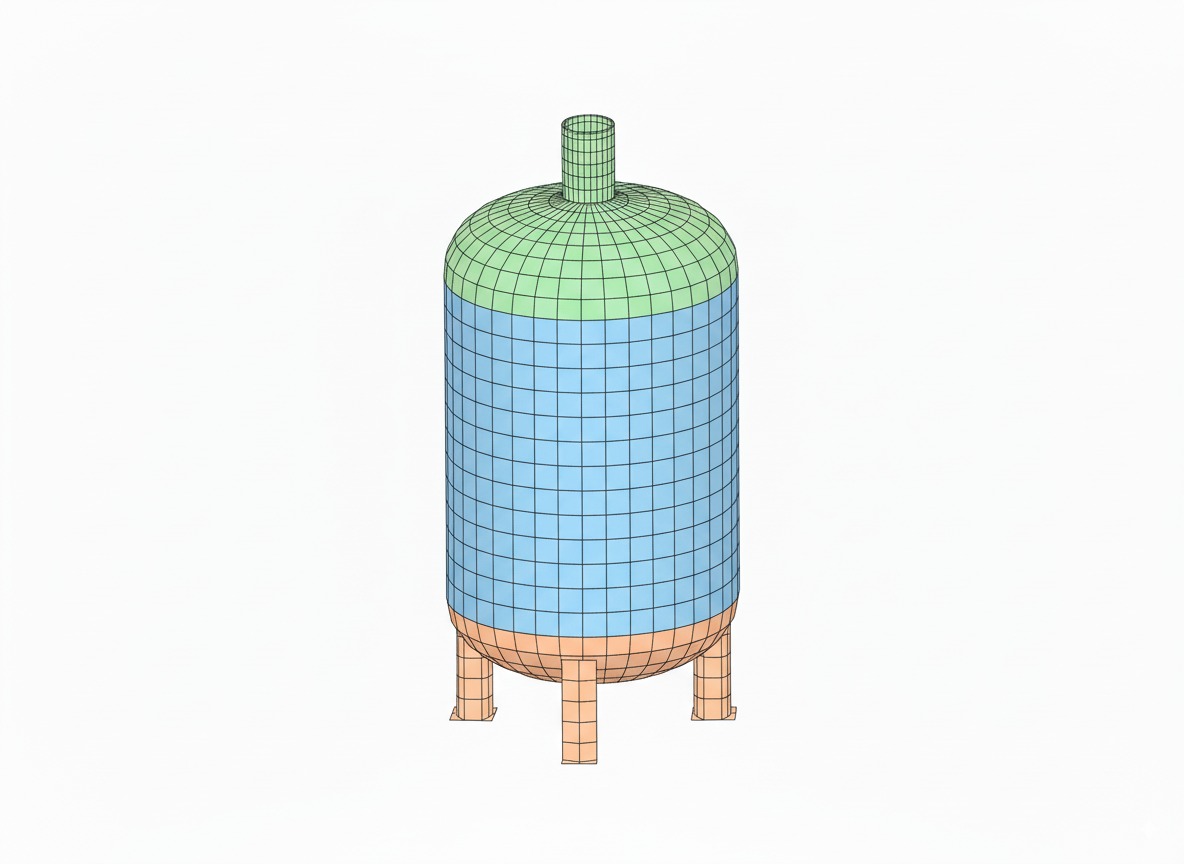
Shell model example: shells are efficient for thin regions but blur through-thickness effects at discontinuities.
Where shells struggle in real vessels
Nozzle–shell junctions. Shell meshes blur the stress peak at the toe and through the thickness, and typically require handbook calculations (e.g., WRC 537/297) to estimate local effects. Even then, analysts from code rules results are too conservative. In many modern layouts, a direct 3D solid model of the junction provides a clearer, less assumption-laden picture.
Saddle supports on horizontal vessels. Zick’s classic method still underpins Division 1 practice and many software tools. It’s invaluable for standard cases, but it simplifies vessel-support interaction and struggles with non-ideal geometry, flexible saddles, or additional global loads. A 3D model naturally picks up edge effects at the horn, contact pressures, and local bending under combined loads.
Thick-to-thin transitions and heavy attachments. The linear through-thickness assumption embedded in shell outputs breaks down for thick regions, blend radii, and high curvature. In these spots, solids with adequate through-thickness refinement resolve the true gradient—and, critically, support elastic–plastic checks when needed.
Fatigue-relevant hot spots. Shells often require stress concentration factors to approximate notch effects for fatigue. High-fidelity solids resolve structural hot-spot stresses directly, improving confidence in fatigue screening and life estimates when paired with code-consistent post-processing.
Why 3D solids match today’s operating reality
Direct capture of 3D load paths. Solid elements let you model the geometry you actually fabricate: nozzle blend radii, pad geometries, flexible saddles, lugs, and gussets. The model, not a stack of factors, carries the physics.
Through-thickness resolution and local failure modes. With solids, you see the inner-to-outer gradient near hot spots and can evaluate peak stresses and plastic penetration properly—key for collapse checks, leak-before-break arguments, and realistic repair decisions.
One model from thin to thick. Modern meshes combine thin shells and thick regions without changing analysis type. Where the wall is thin, parabolic solids capture bending; where it’s thick, they capture the non-linear distribution across the depth.
Aligned with modern design routes. European practice has long offered a Direct Route (EN 13445-3 Annex B) that evaluates failure modes numerically without stress categorization. ASME Division 2 also supports elastic–plastic methods in Part 5 that move away from purely elastic categorization where appropriate. Solids are the natural vehicle for both.

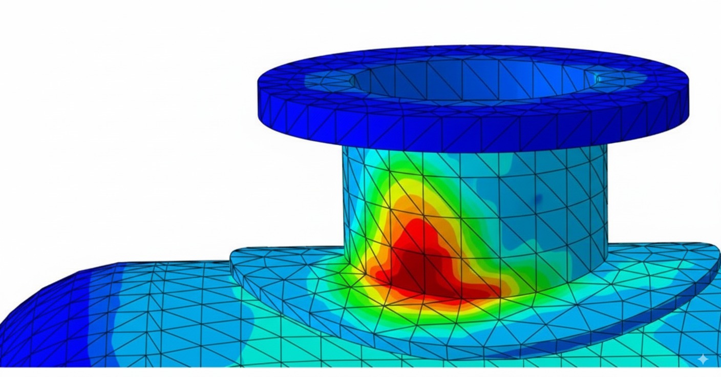
Solid model example: solids recover local hot-spot stresses and gradients.
“Aren’t solids slow?” The performance and element-technology reality
The old objection was runtime and memory. That barrier has largely fallen. Parallel solvers, adaptive meshing, and cloud/HPC options make multi-million DOF analyses routine on project timelines. Just as important, element formulations improved: higher-order (quadratic) solids and solid-shells alleviate classic bending pathologies like shear locking that plagued first-order solid meshes. The practical takeaway is that, with sensible meshing, solids are both feasible and accurate for vessel problems.
Accuracy still demands craft. Linear first-order solids can underestimate bending displacements and distort stress if you don’t stack elements through the thickness or use appropriate formulations. Choose quadratic solids, watch aspect ratios, and ensure at least a few elements through thickness in bending-dominated regions.
A cautionary illustration: direct comparisons of coarse linear solids to shells can produce wildly different displacements and stresses—a numerical artifact, not physics. That isn’t a reason to avoid solids; it’s a reason to use the right order and mesh strategy.
What the codes actually say—and how to make solids “code-ready”
ASME Section VIII Division 2 (Part 5). Division 2’s Design-by-Analysis framework is mature and supported by extensive validation in PTB-1 and worked examples in PTB-3. The elastic route is built around stress categorization (primary membrane, bending, secondary, peak) and stress linearization through the thickness. When you use solids, you are expected to extract membrane/bending components along stress-classification lines for comparison to limits—unless you adopt an elastic–plastic route where categorization is intentionally avoided.
Stress linearization in practice. Many commercial tools include linearization utilities; if not, the procedure is straightforward: define a stress-classification plane through the section, sample through-thickness stress, separate membrane and bending, and compare to Part 5 limits for the relevant failure mode.
EN 13445-3. Europe’s Annex C mirrors the elastic categorization approach; Annex B (Direct Route) dispenses with categorization entirely and assesses failure via limit-load, shakedown, and fatigue checks directly on FEA results. For solids, the Direct Route often means less interpretive overhead.
In short, solids and codes are compatible. The friction is cultural and procedural, not technical. A sound workflow—documented meshing standards, linearization practices, and clear mapping from FEA outputs to code checks—bridges the gap.
When to insist on solids in oil & gas and chemical service
Large or highly loaded nozzles. If your d/D or reinforcement geometry stretches handbook validity, jump to 3D.
Non-standard supports and global+local load interaction. Saddles with atypical spacing, tall wear plates, seismic/shear keys, or significant piping thrusts merit solids to resolve horn stresses, contact zones, and shell ovalization.
Thick-wall segments, transitions, and discontinuities. Skirts with cut-outs, dished head knuckles, flanges, and pad-reinforced openings are poor candidates for shell-only treatment if they govern integrity.
Fatigue screening of hot spots. High-cycle units, temperature-cycling reactors, and compressor bottles benefit from structural hot-spot stresses resolved by solids.
Practical migration: from shell-first habit to solid-first where it counts
Standardize meshing rules. Mandate quadratic solids in bending zones, minimum elements through thickness, and aspect-ratio limits. Use solid-shells where appropriate for very thin regions contiguous with solids.
Embed code mapping. Whether you work under Division 2 or EN 13445, bake linearization or the Direct Route post-processing into templates. Define where to place stress-classification lines, how to handle peak vs. primary stress, and when to escalate to elastic–plastic.
Use shells deliberately. Shells still shine for global stiffness, preliminary sizing, and very thin regions far from discontinuities. A good pattern is global shells + local solids tied together, or a quick shell study to bound loads followed by local 3D sub-models where decisions hinge on accuracy.
Validate and communicate. When shifting practice, nothing beats a side-by-side on a live vessel: run the familiar shell model, then the solid model, and show where the shell is non-conservative or overly pessimistic. Correlate with strain-gauge data at hydro if available to build trust with operations and inspection teams.
A note on pitfalls—and how to avoid them
If a coarse first-order solid mesh reports tiny displacements and oddly low stresses where shells show sensible values, suspect shear locking or hourglassing—not a magically stronger design. The remedy is to switch to higher-order elements, add through-thickness refinement, or use solid-shells where applicable.
Likewise, when adopting solids under Division 2’s elastic route, remember that stress categorization is a code construct, not a physical invariant. Linearization paths and section choices need engineering judgment. If categorization becomes ambiguous at a hotspot that clearly yields locally but not globally, consider the elastic–plastic method in Part 5 or, under EN 13445, the Direct Route.
Bottom line for engineering managers
For assets where unplanned downtime is measured in six figures per day and incidents carry environmental and safety stakes, the analysis method is part of the risk profile. Shell-only workflows were optimized for limitations we no longer have. A solid-first approach for critical regions gives your team clearer visibility of real stresses, fewer hidden assumptions, and better leverage of the design space. It also aligns your practice with the direction of modern standards—without waiting for every paragraph in every code to be rewritten.

Context: petrochemical facilities carry high downtime costs—method fidelity influences risk and spend.
Closing
Pressure vessel engineering is conservative by design, and for good reasons. But conservatism should live in loads, materials, and acceptance criteria, not in the fidelity of our models. The technology to model vessels as they are built—not as simplified midsurfaces—has been here for years. Oil & gas and chemical operators who adopt 3D solid-element analysis where it matters most will make better calls on reinforcements and repairs, avoid both brittle under-design and costly over-design, and document decisions with analyses that withstand scrutiny. That is the standard worth meeting.
