Skip to content

pvcloud

3 posts with the tag “pvcloud”

Are You Still Doing Pressure Vessel Calcs by Hand? Here’s What It’s Costing You.

Are You Still Doing Pressure Vessel Calcs by Hand? Here’s What It’s Costing You.

If you are still building pressure-vessel calculations by hand or stitching them together in Excel, you are paying a tax you cannot see on schedule, quality and reputation. Every hour spent transcribing tables, eyeballing graphs, copying values between sheets or unpicking someone else’s formulas is an hour not spent on design intent, failure modes or scope. Reviewers feel this pain as much as engineers. RPEQs are routinely handed sprawling workbooks with hidden cells, legacy assumptions and no reliable way to trace which version produced the PDF on their desk. The problem is not that spreadsheets are always wrong; it is that you cannot quickly prove they are right. And this cost does not stop at nozzle, it affects routine calculations that make up every real projects.
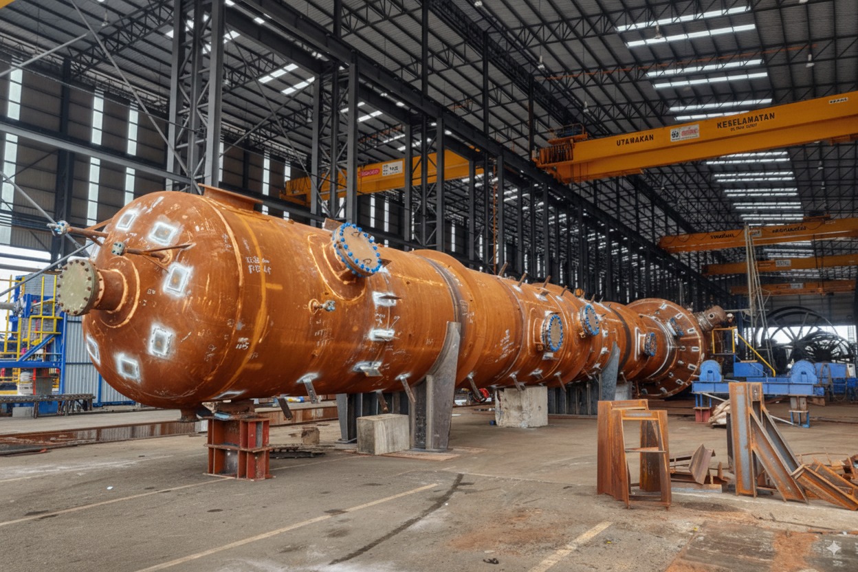
Modern pressure vessel facility at dusk.

Context: production plants carry high downtime costs—clarity and traceability reduce risk.


The Hidden Costs You’re Already Paying

Hidden costs of manual calculations: time loss, rework, review friction.

Context: small frictions—transcription, rework and audit gaps—accumulate into delays and uncertainty.


Manual workflows rarely fail loudly; they leak time and certainty. The first leak is transcription. Engineers move between Code clauses, curve fits and internal check tables, re-typing or copy-pasting values. Even when every number is correct, the task consumes attention better spent on real engineering problem solving deilvers value. The second leak is rework. A late change to a nozzle load case or vessel thickness forces you to thread new numbers through a workbook built earlier for a different geometry. You spend valuable time reacquainting yourself with your own logic before you can safely adjust it. The third leak is review friction. A conscientious reviewer wants evidence that inputs, method and outputs are consistent and traceable. If the workbook does not surface assumptions, Code edition and calculation method on page one, the reviewer slows down and rebuilds trust from first principles. Multiplied across every calculation package in a job, the compounding effect becomes obvious.

Why Spreadsheets Fail in Engineering Contexts

Spreadsheets are powerful and familiar, but they are an undisciplined medium for safety-critical design work. In pressure-vessel practice, the same failure modes recur. Version drift is the most corrosive. Files are emailed, saved to network drives and cloned for similar jobs. Months later, few can say with confidence which workbook created the signed report, or whether it contains the late-stage change the client requested. Hard-coded cells are the quiet killer. A formula replaced with a value during troubleshooting becomes permanent. The spreadsheet still calculates, but the dependency chain is broken and future edits no longer propagate as intended. Unit errors creep in as a single kN entered as N slips through unchallenged. Copy-and-paste mistakes are obvious when they are found and expensive when they are not. A range offset by one row will feed the right-looking number into the wrong place and no one is warned. The same patterns show up whether you are doing a quick WRC check, a head thickness, a nozzle reinforcement or a flange assessment.

Opacity compounds the problem. Spreadsheets make it easy to bury logic behind named ranges and helper tabs. That can be convenient for the author and frustrating for the reviewer who is accountable for the final sign-off. When a calculation cannot be audited quickly, the conservative response is to repeat it independently. Your submission is then treated as an attachment to rather than the basis for approval.

Why Code Tables and Graphs Are Hard to Automate by Hand

Pressure-vessel calculations depend on accepted methods. For nozzle-to-shell checks, WRC 537 and WRC 297 are used every day. The difficulty is not the mathematics; it is the mechanical work of interpreting limits, reading curves and applying the correct set of coefficients for the geometry at hand. When engineers translate those steps into spreadsheets, they recreate the method in fragments: a table entered here, an interpolation there, a chart image pasted as a reminder. Every recreation is a chance to mis-key a coefficient, reference the wrong region or step outside the method’s geometry limits without knowing. Excel can interpolate numbers; it cannot warn you that your d/D or T/t places the case outside the bulletin’s envelope unless you have built, tested and maintained that guardrail for every case.

When Excel Is Still Fine

There is nothing inherently unprofessional about Excel. For one-off scoping exercises, hand checks, early feasibility and simple tests, a small, well-annotated sheet can be more efficient than a full calculator. If you are exploring whether a concept is viable, the overhead of formal documentation can be counterproductive. Excel is also reasonable for stable, mature internal tools when they are tightly controlled, guarded by validation and used by a small, trained group.

The test is simple. If the calculation matters enough to be reviewed outside the author’s immediate team, and if it will be repeated, varied or reused, a spreadsheet starts to work against you. The more stakeholders involved, the more your tool needs to be standardised, self-validating and auditable. That is as true for a nozzle load case as it is for head sizing, reinforcement area or a flange capacity check.

What a Modern, Standardised Workflow Looks Like
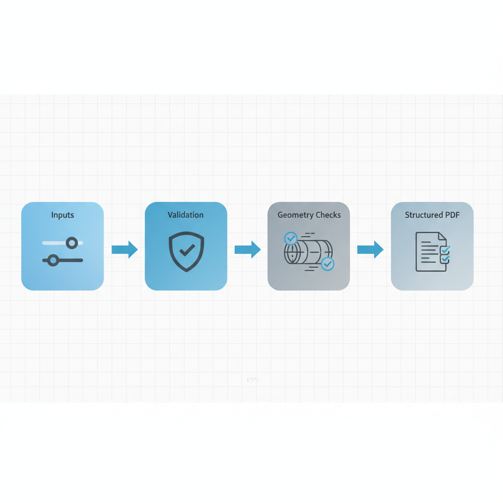
Modern PV Cloud workflow: Inputs → Validation → Geometry Checks → Structured PDF.

Context: structured inputs, automatic validation, geometry checks and a traceable PDF reduce rework and speed review.


A modern workflow does not eliminate engineering judgement; it protects it. The starting point is a purpose-built calculator that implements accepted methods and embeds the tables and curve-fit equations rather than asking the user to transcribe them. It checks geometry limits up front and reports when the method does not apply. It treats units explicitly, validates inputs as they are entered and makes assumptions visible. It records the calculation version, the Code edition and the user who ran it.

The outputs are structured and repeatable. Inputs, method and results are captured in a report that reads the way a reviewer thinks. The PDF references the calculator version and change log. If a change is made, regenerating the report creates a new entry that records what changed and when. Sharing is deliberate. A reviewer receives an authoritative record, not a forked spreadsheet they will inevitably edit. If a new load case is required, it can be created without breaking the original record.

Moving from Excel to PV Cloud Without Disruption

If you want to see the difference on real work, start with the WRC 107/297/537 nozzle calculator in PV Cloud, run your next case and compare the experience and the output to your current spreadsheet. You will spend less time wrestling, and more time doing engineering—and you will produce a report a reviewer can trust months from now when the job is revisited.

Use the nozzle calculator free here: https://pv-cloud.com


Closing

Pressure-vessel engineering will always require judgement. That judgement deserves a workflow that does not dilute it with transcription, version drift and audit gaps. PV Cloud makes the accepted methods easier to apply, the limits harder to miss and the results simpler to review. The outcome is not a shortcut around RPEQ sign-off; it is a higher-quality submission to it—delivered faster, with fewer surprises, and with a traceable record you can defend.

Pressure Vessel FEA: Why Shell Elements Alone Are No Longer Enough

Introduction

Pressure Vessel FEA for Oil & Gas and Chemical: Why Shell Elements Alone Are No Longer Enough

For decades, 2D shell-element models have been the workhorse of pressure vessel analysis. They were fast, familiar, and aligned with the way design codes framed stresses. That legacy is now a limitation. Modern pressure vessels in oil & gas and chemical service face complex load paths, thick-to-thin transitions, and demanding integrity targets. With today’s computing power and FEA tooling, 3D solid-element models capture behaviors that 2D shells inherently miss, especially around nozzles, supports, and discontinuities. Codes such as ASME BPVC Section VIII, Division 2 (Part 5) and EN 13445-3 already provide routes to leverage modern analysis, but their stress-categorization heritage and documentation lag still nudge practice toward shells. It’s time to normalize solids as the default for critical cases—and use shells deliberately, not by habit.


What shell elements got right—and why they’re no longer sufficient

Shells earned their place because most vessels are thin-walled, and shell theory maps neatly to hoop/membrane/bending checks. In the era of limited CPU resources, shells were the pragmatic choice, especially when codes and in-house standards were written with shell stress categories front and center. That history still shapes workflows today.

The shortcoming is fundamental: a shell is a midsurface with an assigned thickness. It will not resolve through-thickness gradients at hot spots or reconstruct 3D load flow through complex junctions. Analysts compensate with hand formulas, SIFs, or WRC bulletins around nozzles and attachments—but each workaround is an approximation stacked on a simplification. As designs and operating envelopes have grown more complex, those approximations can become the dominant source of uncertainty.

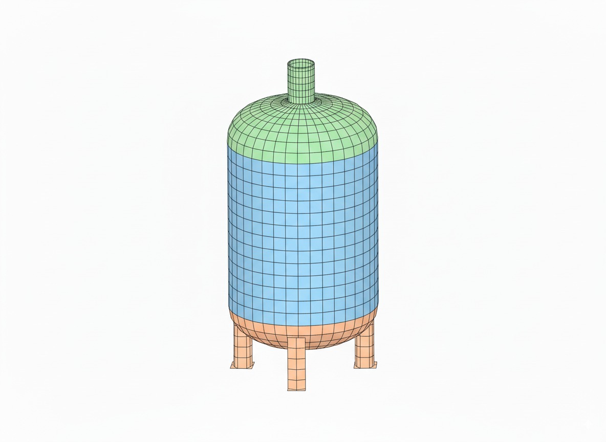
2D shell element vessel midsurface model.

Shell model example: shells are efficient for thin regions but blur through-thickness effects at discontinuities.


Where shells struggle in real vessels

Nozzle–shell junctions. Shell meshes blur the stress peak at the toe and through the thickness, and typically require handbook calculations (e.g., WRC 537/297) to estimate local effects. Even then, analysts from code rules results are too conservative. In many modern layouts, a direct 3D solid model of the junction provides a clearer, less assumption-laden picture.

Saddle supports on horizontal vessels. Zick’s classic method still underpins Division 1 practice and many software tools. It’s invaluable for standard cases, but it simplifies vessel-support interaction and struggles with non-ideal geometry, flexible saddles, or additional global loads. A 3D model naturally picks up edge effects at the horn, contact pressures, and local bending under combined loads.

Thick-to-thin transitions and heavy attachments. The linear through-thickness assumption embedded in shell outputs breaks down for thick regions, blend radii, and high curvature. In these spots, solids with adequate through-thickness refinement resolve the true gradient—and, critically, support elastic–plastic checks when needed.

Fatigue-relevant hot spots. Shells often require stress concentration factors to approximate notch effects for fatigue. High-fidelity solids resolve structural hot-spot stresses directly, improving confidence in fatigue screening and life estimates when paired with code-consistent post-processing.


Why 3D solids match today’s operating reality

Direct capture of 3D load paths. Solid elements let you model the geometry you actually fabricate: nozzle blend radii, pad geometries, flexible saddles, lugs, and gussets. The model, not a stack of factors, carries the physics.

Through-thickness resolution and local failure modes. With solids, you see the inner-to-outer gradient near hot spots and can evaluate peak stresses and plastic penetration properly—key for collapse checks, leak-before-break arguments, and realistic repair decisions.

One model from thin to thick. Modern meshes combine thin shells and thick regions without changing analysis type. Where the wall is thin, parabolic solids capture bending; where it’s thick, they capture the non-linear distribution across the depth.

Aligned with modern design routes. European practice has long offered a Direct Route (EN 13445-3 Annex B) that evaluates failure modes numerically without stress categorization. ASME Division 2 also supports elastic–plastic methods in Part 5 that move away from purely elastic categorization where appropriate. Solids are the natural vehicle for both.

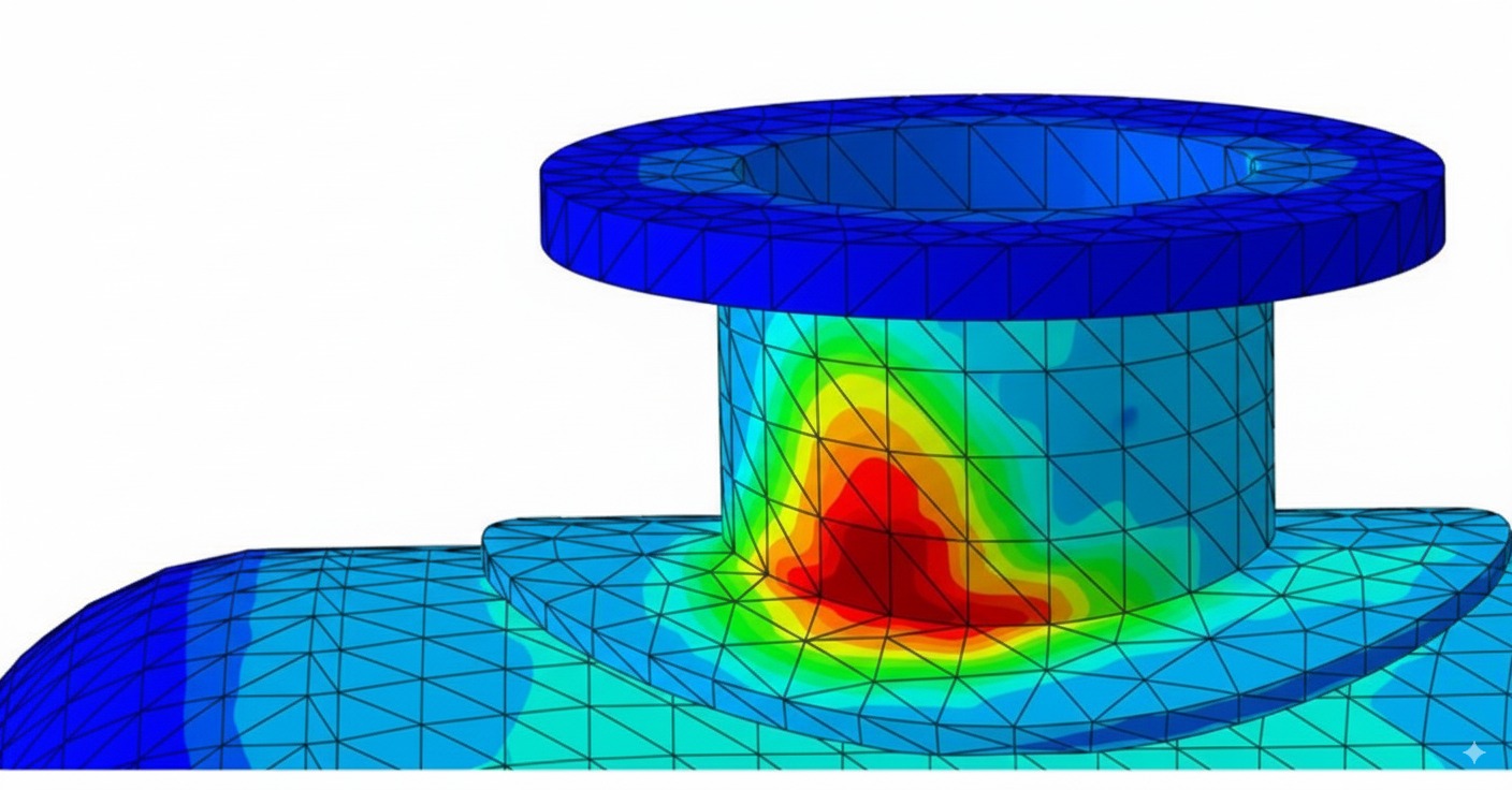
3D solid elements at nozzle weld toe showing von Mises peak.

Solid model example: solids recover local hot-spot stresses and gradients.


“Aren’t solids slow?” The performance and element-technology reality

The old objection was runtime and memory. That barrier has largely fallen. Parallel solvers, adaptive meshing, and cloud/HPC options make multi-million DOF analyses routine on project timelines. Just as important, element formulations improved: higher-order (quadratic) solids and solid-shells alleviate classic bending pathologies like shear locking that plagued first-order solid meshes. The practical takeaway is that, with sensible meshing, solids are both feasible and accurate for vessel problems.

Accuracy still demands craft. Linear first-order solids can underestimate bending displacements and distort stress if you don’t stack elements through the thickness or use appropriate formulations. Choose quadratic solids, watch aspect ratios, and ensure at least a few elements through thickness in bending-dominated regions.

A cautionary illustration: direct comparisons of coarse linear solids to shells can produce wildly different displacements and stresses—a numerical artifact, not physics. That isn’t a reason to avoid solids; it’s a reason to use the right order and mesh strategy.


What the codes actually say—and how to make solids “code-ready”

ASME Section VIII Division 2 (Part 5). Division 2’s Design-by-Analysis framework is mature and supported by extensive validation in PTB-1 and worked examples in PTB-3. The elastic route is built around stress categorization (primary membrane, bending, secondary, peak) and stress linearization through the thickness. When you use solids, you are expected to extract membrane/bending components along stress-classification lines for comparison to limits—unless you adopt an elastic–plastic route where categorization is intentionally avoided.

Stress linearization in practice. Many commercial tools include linearization utilities; if not, the procedure is straightforward: define a stress-classification plane through the section, sample through-thickness stress, separate membrane and bending, and compare to Part 5 limits for the relevant failure mode.

EN 13445-3. Europe’s Annex C mirrors the elastic categorization approach; Annex B (Direct Route) dispenses with categorization entirely and assesses failure via limit-load, shakedown, and fatigue checks directly on FEA results. For solids, the Direct Route often means less interpretive overhead.

In short, solids and codes are compatible. The friction is cultural and procedural, not technical. A sound workflow—documented meshing standards, linearization practices, and clear mapping from FEA outputs to code checks—bridges the gap.


When to insist on solids in oil & gas and chemical service

Large or highly loaded nozzles. If your d/D or reinforcement geometry stretches handbook validity, jump to 3D.

Non-standard supports and global+local load interaction. Saddles with atypical spacing, tall wear plates, seismic/shear keys, or significant piping thrusts merit solids to resolve horn stresses, contact zones, and shell ovalization.

Thick-wall segments, transitions, and discontinuities. Skirts with cut-outs, dished head knuckles, flanges, and pad-reinforced openings are poor candidates for shell-only treatment if they govern integrity.

Fatigue screening of hot spots. High-cycle units, temperature-cycling reactors, and compressor bottles benefit from structural hot-spot stresses resolved by solids.


Practical migration: from shell-first habit to solid-first where it counts

Standardize meshing rules. Mandate quadratic solids in bending zones, minimum elements through thickness, and aspect-ratio limits. Use solid-shells where appropriate for very thin regions contiguous with solids.

Embed code mapping. Whether you work under Division 2 or EN 13445, bake linearization or the Direct Route post-processing into templates. Define where to place stress-classification lines, how to handle peak vs. primary stress, and when to escalate to elastic–plastic.

Use shells deliberately. Shells still shine for global stiffness, preliminary sizing, and very thin regions far from discontinuities. A good pattern is global shells + local solids tied together, or a quick shell study to bound loads followed by local 3D sub-models where decisions hinge on accuracy.

Validate and communicate. When shifting practice, nothing beats a side-by-side on a live vessel: run the familiar shell model, then the solid model, and show where the shell is non-conservative or overly pessimistic. Correlate with strain-gauge data at hydro if available to build trust with operations and inspection teams.


A note on pitfalls—and how to avoid them

If a coarse first-order solid mesh reports tiny displacements and oddly low stresses where shells show sensible values, suspect shear locking or hourglassing—not a magically stronger design. The remedy is to switch to higher-order elements, add through-thickness refinement, or use solid-shells where applicable.

Likewise, when adopting solids under Division 2’s elastic route, remember that stress categorization is a code construct, not a physical invariant. Linearization paths and section choices need engineering judgment. If categorization becomes ambiguous at a hotspot that clearly yields locally but not globally, consider the elastic–plastic method in Part 5 or, under EN 13445, the Direct Route.


Bottom line for engineering managers

For assets where unplanned downtime is measured in six figures per day and incidents carry environmental and safety stakes, the analysis method is part of the risk profile. Shell-only workflows were optimized for limitations we no longer have. A solid-first approach for critical regions gives your team clearer visibility of real stresses, fewer hidden assumptions, and better leverage of the design space. It also aligns your practice with the direction of modern standards—without waiting for every paragraph in every code to be rewritten.

3D solid elements at nozzle weld toe showing von Mises peak.

Context: petrochemical facilities carry high downtime costs—method fidelity influences risk and spend.


Closing

Pressure vessel engineering is conservative by design, and for good reasons. But conservatism should live in loads, materials, and acceptance criteria, not in the fidelity of our models. The technology to model vessels as they are built—not as simplified midsurfaces—has been here for years. Oil & gas and chemical operators who adopt 3D solid-element analysis where it matters most will make better calls on reinforcements and repairs, avoid both brittle under-design and costly over-design, and document decisions with analyses that withstand scrutiny. That is the standard worth meeting.

WRC 537 vs WRC 297: Finally Making Sense of Nozzle Stress Calculations

Pressure vessel

Why these bulletins matter

Specifications still lean on Welding Research Council bulletins when they talk about nozzle loads. That legacy can be helpful or it can slow you down. The purpose of using these methods is to calculate stresses in the vessel and at the nozzle in a way that aligns with code intent and supports sound engineering decisions. When the wrong bulletin is chosen, questions multiply, reviewers hesitate, and projects lose time. When the right one is applied, the discussion becomes simpler: everyone can see what is being calculated, why it is valid for the geometry, and where its limits are. The most practical outcome is knowing where the bulletins end and where finite‑element analysis begins.

WRC 107 in practice (legacy method)

For decades, WRC 107 supplied local shell stresses around attachments using families of charts and equations. It is part of how many engineers learned to quantify nozzle loads and it served industry well. But WRC 107 never reported stresses in the nozzle itself, and it can under‑represent nozzle demand when the geometry stretches its assumptions. In particular, when a reinforcement pad is present or the nozzle is relatively thin compared with the shell, the peak may migrate into the nozzle and a supplemental evaluation is required. In modern practice, WRC 107 survives mostly as a name people remember while the method itself lives on in its successor.

WRC 107 → WRC 537 (what changed)

In 2010, WRC 537 superseded WRC 107. The update modernized curve fits and clarified limits without changing the essence of the approach. It remains a method for calculating stresses in the vessel shell due to external loads on attachments. If a specification still cites WRC 107, treat that reference as legacy language and use WRC 537. Doing so not only improves clarity but also aligns your documentation with what reviewers expect to see today.

WRC 537, WRC 297, or both?

This is the question that causes most confusion and most rework. WRC 297 has a narrow but important purpose: it treats two normally intersecting cylindrical shells, meaning a radial cylindrical nozzle attached to a cylindrical vessel. It is focused on the nozzle junction. Even WRC 297 acknowledges that the accepted procedure for calculating shell stresses from applied nozzle loads is the method that originated in WRC 107 and now resides in WRC 537. In practice, if you have the classic radial cylinder‑on‑cylinder connection, you use WRC 297 to obtain nozzle stresses and WRC 537 to obtain vessel stresses. Together they give a complete and code‑aligned picture for that geometry.

Where WRC 537 applies

WRC 537 covers cylindrical shells with round and rectangular hollow attachments and their solid counterparts. It also covers spherical shells with round or square attachments, while ellipsoidal heads are treated as spherical using the mean radius at the attachment point—a practical approximation that produces reasonable accuracy. One limitation is explicit and easy to miss when skimming: WRC 537 gives stresses in the shell, not in the nozzle. If nozzle stresses are required, you either combine it with WRC 297 for the radial cylinder‑on‑cylinder case or you step into FEA when the geometry falls outside that narrow scope.

Quick selection guide

A simple way to navigate the choice is to start with geometry. If the vessel is cylindrical and the nozzle is a radial cylinder, pair WRC 297 for the nozzle with WRC 537 for the shell. If the attachment is non‑cylindrical, or the vessel is spherical or ellipsoidal, WRC 537 alone provides the vessel stresses and you address nozzle stresses separately—often with a small, targeted finite‑element model. When the connection departs from radial, such as hillside nozzles on small radius vessels or lateral connections, forcing the bulletins to fit tends to produce more questions than answers and FEA quickly becomes the cleaner path to clarity.

When the bulletins are not enough

The bulletins were written for single‑attachment, idealized cases. They do not capture interaction between nearby openings, complex reinforcement details, or the combined effects of external loads with pressure on a flexible shell. Clustered nozzles, stiffness transitions, and mixed loading are exactly the situations where a short 3D analysis pays back the setup time. A simple model can validate stresses and deflections in hours rather than days of debate over the edges of a chart.

Common pitfalls to avoid

Treating WRC 297 as a standalone answer is the fastest way to land in review purgatory. For the classic radial cylinder‑on‑cylinder case it belongs alongside WRC 537, which supplies the vessel stresses the code expects to see. Leaving WRC 107 in specifications also creates churn; update the language to WRC 537. And do not ignore the bounds of the methods. Thickness ratios, diameter ratios, and other parameters form the envelope within which the calculations are credible. When geometry or loads strain those limits, acknowledge it and escalate to FEA.

The path forward

As design cycles compress and digital workflows mature, the most effective practice is to use the bulletins where they are strong and move to FEA when geometry or loading becomes atypical. Knowing precisely what WRC 537 and WRC 297 provide helps you validate software outputs, communicate with clients and reviewers, and decide when simplified methods truly suffice. The result is fewer surprises late in the project, less rework, and documentation that aligns with code expectations without over‑promising what a chart can do.

Key takeaways

WRC 537 has replaced WRC 107 and should be your default reference for vessel shell stresses. WRC 297 applies to the radial cylinder‑on‑cylinder nozzle and, when it applies, it belongs alongside WRC 537. Many configurations are adequately treated by WRC 537 alone for vessel stresses, but nozzle‑stress questions and complex geometries benefit from finite‑element analysis. Use the standards as tools, not as a cage—engineering judgment closes the gaps.

Run WRC 537 and 297 with PV Cloud

Stop stitching spreadsheets together. PV Cloud runs WRC 537 (shell checks) and WRC 297 (nozzle junction) side‑by‑side today, providing code‑aligned calculations. FEA validation is coming soon to PV Cloud.

Calculate with PV Cloud →